Sample thickness#
The ices are deposited for 20 minutes and during deposition, the pressure in the PAC is regulated between 1 – 1.2 × 10⁻⁷ mbar. In situ laser measurements are aquired using a monocromatic laser (HeNe) directed toward the center of the sample holder and reflected to a photodiode. Interference patterns arising from the constructive and destructive interference of the growing sample are recorded manually during deposition. The purpose of this reduction step is to fit the resulting data and get an average value of the sample thickness.
Note
There is better method to do that
Double beam
RAIRS
Workflow#
 laser-diode_{}.csv
 Thickness-calc_{}_1
Data Import and Cleaning#
The Raw data is of the shape
We aquire one data point every 30s
Note
Insert here the data
Export some example datasets to show the format
Fitting#
The purpose of the notebook is to fit the data of laser-diode_{}.csv
\(y_0\) is the vertical offset,
\(A\) is the amplitude,
\(x_c\) is the horizontal offset,
\(w\) is the period (i.e. \(2\pi/w\) is the frequency)
We define the sine function sinfit(x, *p) for the fit with some initial guesses, which can be edited accordingly.
‣ Example 2020_09_16 #
‣ ‣ Thickness Calculation 1 #
For this step we use the full range and it gives:
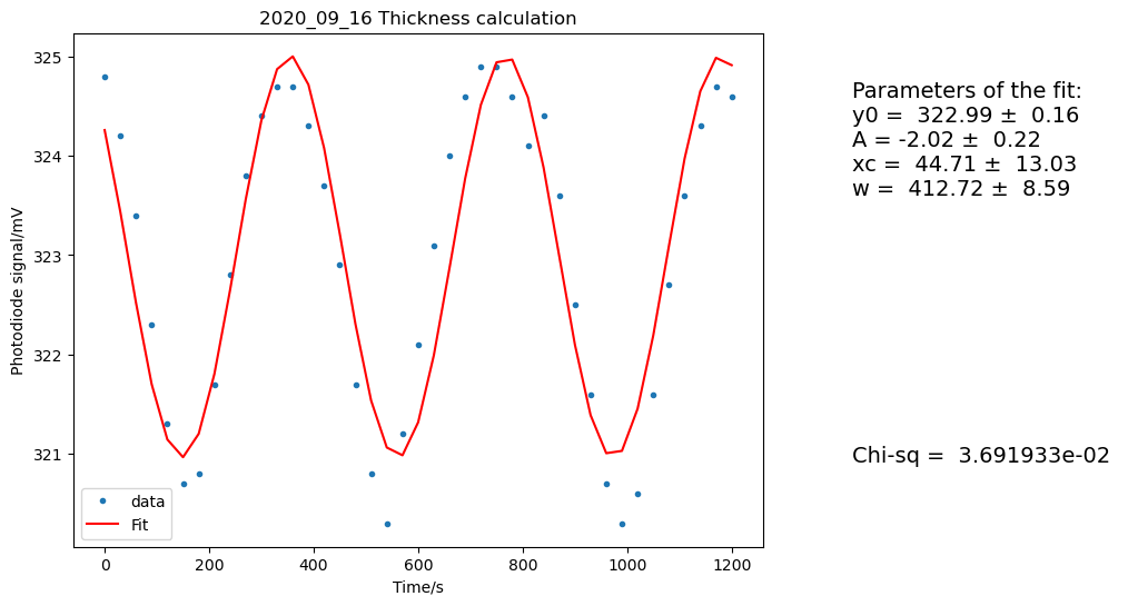
Fig. 49 Thickness calculation 1 for 2020_09_16 sample#
‣ ‣ Thickness Calculation 2 #
For this second step, we reduce the range so that it only contains the beginning (more reliable) part of the interference spectrum. In this case I have selected a range of:
0 < time (s) < 540
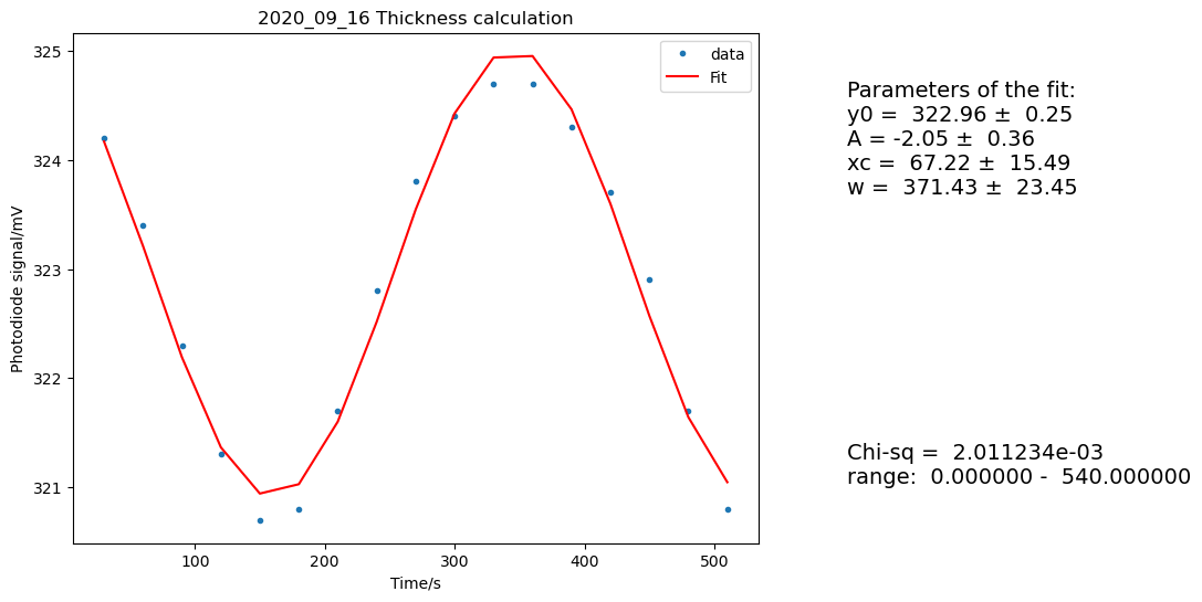
Fig. 50 Thickness calculation 2 for 2020_09_16 sample#
Extra calculations#
Note
May be should go in DR3
Optical Depth#
τυ is the optical depth and is equal to ln(10) times the integrated absorbance
Column Density#
N (mollecule cm-2)
A is the band strength in cm molecule−1