Interferometry#
Ice thickness is determined by in-situ laser measurment (e.g. HeNe laser with a fixed wavelength of λ0 = 632.8 nm). The laser beam is positioned so that it reflects off the centre of the substrate and the reflected beam is measured with a photodiode
Note
Include diagram of the setup
position of the laser
position of the detector
As monochromatic light is shone onto an ice film, the light can be reflected from the vacuum-ice interface or the ice-substrate interface. The reflected light sin-waves interacts and interference patterns appears due to the constructive and destructive interference arising from the increasing ice thickness as shown in Fig. 28.
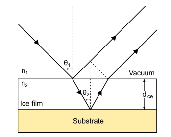
Fig. 28 Taken from Rachael, to redo#
Note
add svg sin wave to show constructive, destructive interference
where \(y_0\) is the vertical offset, \(A\) is the amplitude, \(x_c\) is the horizontal offset and \(w\) is the period (i.e. \(2\pi/w\) is the frequency).
We define the sine function ‘sinfit(x, *p)’ for the fit with some initial guesses, which can be edited accordingly.
A is obtained from the fit
Then we can estimate the refractive index of the ice (n2), can be estimated using the following equation
Using Snell’s Laaw (\(n_1 sinθ_1 = n_2 sinθ_2\))
Warning
Difference in fitting from different molecules
single vs binary mixtures
To see how this is translated into code visit the folloing page []