Novel methodology for producing amorphous ice micro-particles - Proof of concept experiment#
Overview and aim#
Bulk properties of amorphous ices upon collisions is assumed to be less elastic than crystalline ice [], thus providing a potential solution to overcoming the bouncing barrier for grains around cm size. However, collision properties of amorphous ice coated grains relevant to those found in the midplane of protoplanetary disks has never been investigated. This is due to the difficulty to produce, use and store such samples that are metastable under Earth conditions. ASW is commonly produced by water vapor deposition on a cold plate up to few monolayers (ML) due to the heat of condensation that needs to be transmitted into the cold surface. Bar-Nun overcame this issue by scraping the surface when the sample was 200 µm thick with a cold knife, introducing it in a sample container maintained at Liquid nitrogen temperature thus, producing 5- 10 cm thick samples [] (Bar Num). This method has been used to study the bulk properties of comets but is not suitable to produce pebble like samples, necessary to perform collisions. Another way to produce vitreous ice involves rapid freezing (quenching) from the liquid phase, where the size and shape of the frozen sample, named Hyperquenched Glassy Water (HGW), is determined and controlled by the initial liquid droplet. HGW and compact ASW have similar properties (citations) and thus can be considered good analogues of each other. However, water is a poor glass former and consequently, needs a very fast cooling rate to be vitrified, typically of the order of 106 K/s (citations). Brüggeller and Mayer (1980) were the first to achieve the complete vitrification of water droplets by spraying them into organic cryogenic liquids. This technique has since been improved by cryo-biologist intending to freeze living samples to be seen in Electron microscopy while avoiding artefacts due to crystallization and have been awarded the Nobel prize in chemistry in 2017 (Dubochet and McDowall 1981). I aim to adapt this method in order to produce µm amorphous ice grain for Astronomical purposes. The range of application is extremely broad, spanning from microgravity collision experiments to decipher the processes of planet formation, to the determination of optical constants of 3D amorphous ice, a key aspect to process future JWST Data (citations). In this chapter I will describe two experiments that I have designed to produce ASW grains; a proof of concept will be discussed first in section 5.3 before going on to describe the second version in section 5.4 and its procedure in section 5.5. A brief Introduction to the theory of cooling and an evaluation of both experiments will be respectively debated in sections 5.2 and 5.6.
Proof of concept experiment#
The overall aim of this experiment is to produce and introduce µm size water droplets into a liquid cryogen maintained at cold temperature to vitrify them similarly to the spray-freeze-etching method developed by Bachman [] with the difference that ethane is used as cryogen and not propane, as being done by Mayer [].
Water droplet production -> 3D spherical samples.
Cryo-SEM sample preparation usually requires cooling of a sample holder (holding the sample) (citation), to be subsequently introduced into the microscope without further manipulation. The method used in this proof of concept experiment work towards direct freezing into the cryogen of a large number of samples (calculation of number of individual µm droplets from 10 ml), prior to storage in liquid nitrogen for future manipulation or characterization. This imply the design of a “recovery method” to retrieve and separate the water ice particles from the cryogen (liquid ethane).
Safety consideration#
Ethane is a flammable gas and for that reason, the experiment has thus to be handled in a Glove Box (GB) to avoid the dispersion of ethane into the laboratory. The glove box is continuously purged with dry nitrogen gas to decrease the amount of oxygen, thus getting below the lower flammability limit of ethane, 3 % at atmospheric pressure []. This also prevents contamination of water moisture from the atmosphere, which is necessary as some of the experiments are performed using heavy water (D2O). I have also taken the utmost care to minimize potential spark sources by having no electrical devices within the glove box and earthing all the outer metal parts. Also, the gloves are made of butadyl, a static dissipative material. Overall, after filling a Sevron Risk Assessment RA816548 (Annex?), the risk is evaluated as low.
Design and operation#
Fig. 1 shows the overall proof of concept experimental setup, which will be described in detail in this section, together with the detailed experimental procedure and the order of operation. The main experimental is divided into 4 steps, represented by the different colored rectangles in Fig. 1:
Ethane liquefaction (green)
Water droplet production (dark blue)
Water droplet introduction (light blue) and
Sample recovery (red)
Each of these steps will be described in turn in the following paragraphs, but first a general description of the experimental set up is given, together with details on setting up the ideal working environment within the glove box. The glove box is divided into two parts, the main chamber P1 and an airlock chamber P2. P1 is the main working space and contains the reaction vessel (indicated with the green square containing parts labelled 1, 2, 3 and 4) and the recovery dewar (highlighted in light red, DR). P2 is a self-contained chamber connected to P1 via an air-tight door the purpose of which is to extract the recovered sample (DR) without releasing too much ethane into the laboratory. P1 has a bolted front door, that can allow all the material needed to be put inside the glove box (list of the material) prior to beginning of the experiment. Both chambers are purged with nitrogen gas from the same gas cylinder, with its pressure set via a two-stage gas regulator at 0.2 bar (Value to check – Do I speak about Extraction ¼” pipe - Carbon trap? – main lab exhaust). 30 minutes of purge is necessary to decrease the O2 levels in the main chamber below the 3% representing the lower flammability limit of ethane. To monitor the oxygen levels while purging, a portable oxygen alarm is introduced into the glove box. Once the initial purge is achieved the N2 flow is decreased to provide good working conditions, for example, a pressure set up too high will inflate the gloves thus reducing handling abilities within the glove box. However, a small nitrogen flow needs to be present at all time, maintaining a slight overpressure and preventing any air (containing O2) from entering the glove box.
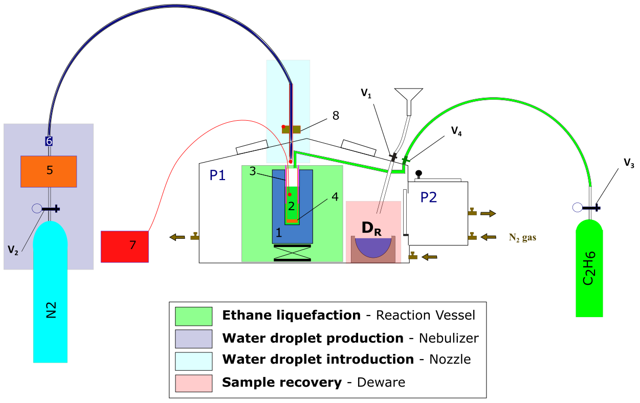
Fig. 1 Diagram of proof of concept experiment. Colored squares represent the different setups associated with the different part of the procedure; green: ethane liquefaction; dark blue: water droplet production; light blue: water droplet introduction; red: sample recovery and transfer. Numbers will be explained later in the text.#
The only time when the purge is stopped during the procedure is when liquid nitrogen needs to be introduced inside the Glove box, a preliminary step before ethane liquefaction and sample recovery. The reason being that when poured in a warm container, (1) in Fig. 1 and Fig. 2, liquid nitrogen evaporates quickly with a liquid to gas ratio 1:694 (citation). Liquid nitrogen is taken from a pressurized Dewar, filtered using a tea towel into a polystyrene container (2L volume) and brought to the lab. A funnel (right corner of P1), connected to the glove box via a cryogenic ball valve (V1) is used to introduce the liquid nitrogen. A plastic tube (material 10 cm long) is connected to the valve inside the glove box to channel the liquid into the Dewar flask. Once the N2 purge is temporary paused, pressure must be applied on the gloves to decrease the overall volume of the glove box. A small amount of liquid nitrogen can then be poured into the funnel (V1 being closed). This can lead to some turbulent outpouring resulting from the initial cooling of the funnel and appropriate PPE (Personal Protective Equipment) must be worn at all times. Also, some bubble wrap and tea towels are disposed around the funnel preventing falling liquid nitrogen to get in contact with the glove box walls. V1 can then be opened and liquid Nitrogen introduced into the Dewar. Because of the Dewar being initially at room temperature, most of the liquid Nitrogen will evaporate, increasing the pressure within the glove box. Deflating the gloves and stopping the purge before introducing the liquid nitrogen allows for control of gas volume within the glove box. Indeed, the evaporating liquid nitrogen will first result in the glove inflation, thus counterbalancing the temporary increase in pressure. If too much LN2 is initially introduced into the funnel, the gloves will inflate fully thus increasing the pressure inside the glove box, preventing the liquid to flow through the valve. This can represent an explosion hazard that must be prevented by filling the Dewar (1) gradually, and not introducing too much nitrogen in the funnel each time, particularly at the beginning of the experiment where everything is warm. Before every funnel refilling with nitrogen, it is important to make sure that the gloves are fully deflated by pressing on them with V1 open. This operation must be patiently repeated 4 times to fill the 1L Dewar (1).
Ethane liquefaction#
Ethane is commercially available as gas .
Warning
(CAS info etc, where do I get it from need to ask Tom on return, proper licensing is needed to get access to ethane delivery)
What kind of regulator, Ethane acheminated through a 1/8“ pipe, flashback arrester to avoid reflux of gas inside bottle safety.
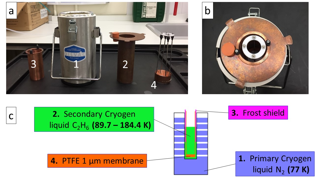
Fig. 2 a) Separate pieces of cooling setup: (1) Dewar vessel, liquid N2 bath – primary cryogen (2) Custom reaction vessel for C2H6 – secondary cryogen (3) Frost shield (4) basket – PTFE 1 µm membrane; b) Assembled cooling setup; c) Schematic diagram of the cooling setup#
Ethane is liquid between 89.7 K and 184.4 K at atmospheric pressure (citation). Liquefaction is achieved by introducing ethane gas in a reaction vessel (2), cooled to 77 K by submersion in liquid nitrogen contained in (1). (3) is a frost shield, the purpose of which is to catch frost that inevitably grows from the water vapour present within the glove box (even with the purge on), sticking on the cold metal parts of the reaction vessel (2). This is necessary to prevent frost from falling into the cryogen, as this would be a source of impurity. (4) is a PTFE membrane containing 1 μm sized pores, screwed at the bottom of a custom-made basket that is used to fish out the particles from the cryogen. (2), (3) and (4) are made of copper, a high thermal conductive metal (thermal conductivity of 401 W/m/K at 273K (citation – value taken from Wikipedia)), allowing for efficient thermal transfer. They must be put in place as shown in Figure 2 (b) prior to the initial cooling phase, basket (4) being introduced first followed by the frost shield (3). Because they are made of the same material (copper), mechanical stress due to differential shrinking resulting from exposure to cold temperature is prevented.
Once (1) is filled with liquid nitrogen as described previously, (2) is slowly submerged into (1) to progressively cool it down. This part of the procedure can be quite time-consuming (10-15 min) and posing risks because cooling (2) greatly enhances nitrogen evaporation which in turn increases the pressure within the GB inflating the gloves. I overcome this issue by holding and dipping the reaction vessel with one hand inside the glove box while keeping my other hand out in order to externally open or close V1 to release the overpressure. Cryogenic gloves must be worn inside the glove box (over the top of the glove box gloves) to prevent injuries from prolonged contact with cold temperatures. Cooling of the reaction vessel at liquid nitrogen temperature (77K) is identified by an intense evaporation event (Leidenfrost effect?), followed by the liquid nitrogen becoming quiescent. This phase usually results in the evaporation of most of liquid nitrogen which can be topped up in (1), to no more than 2/3 of the level to account for the volume of the reaction vessel.
Once the reaction vessel is at liquid nitrogen temperature 77K, ethane gas is introduced into (2) via a movable copper pipe from the ethane gas bottle fed through the glove box via the valve (V4). This is done by first, opening the gas bottle, followed by the gas regulator and finally the valve V4. Ethane pressure is monitored using a digital pressure gauge which is connected between the gas regulator and V4. The ethane introduction is characterized by the appearance of a thick fog of ethane microdroplets within the reaction vessel (as shown in figure 15 – figure is far away but don’t have similar picture with this setup … - bringing figure 15 here could create confusion between the two experiments). This fog is strongly influenced by the incoming ethane gas flow. Indeed, an ethane pressure set up too high will result in turbulent convection into the reaction vessel blowing out from it most of the liquid droplets, thus reducing the liquefaction efficiency. To achieve ideal flow conditions, ethane pressure is adjusted using the regulator to around 100 mbar to achieve a smooth introduction as shown in Figure 15 b).
:::{note} Insert figure ethane T evolution :::
A K-type thermocouple is attached to the frost shield (3) to monitor the ethane temperature and is shown in Figure 3. The liquid ethane temperature is not stable and constantly increases because the cooling setup never reaches a state of equilibrium. This is due to the constant evaporation of the primary cryogen, liquid nitrogen, since its boiling temperature, 77 K is lower than the melting point of ethane, 89.7 K. It is therefore necessary to refill the liquid nitrogen in (1) every 30 minutes. (2) needs to be lifted out of (1) and carefully re-inserted once (1) is refilled. This procedure must be repeated 4 times (as can be seen in Figure 3) until the desired amount of liquid ethane has been reached corresponding to ¼ L, or a filling level 2 to 3 cm below the top of the reaction vessel. This operation takes 2 hours to be completed. Before the next step, where water droplets are introduced into the cryogen, liquid nitrogen can be topped up as necessary if the temperature is too high. The ethane pipe has to be removed from inside the reaction vessel, with its height adjusted with a lab jack to move it closer to the nozzle.
Water droplet production and introduction#
Two goals need to be achieved regarding the water droplet production. First, the droplets must be small, in the order of a few micrometer to perform an optimal vitrification (Explain why – fewer chances of getting impurity – reduce chances of impurity per droplets, sources of heterogeneous nucleation, also smaller sample will cool quickly). What is the purity of the water used? – triple distilled water? Cleaning procedure, can the droplets get impurity from their way towards the cryogen … Secondly, they need to be introduced at relatively high speed to be deeply embed in the cryogen thus improving the forced convection thermal transfer (source). Both of those objectives can be achieved using commercially available nebulizers. Those devices are commonly use in drug delivery to lungs (Why? source). Droplet size relate to alveolar absorption … Liquid nebulization is achieved by the application of a dispersing force on a liquid or solution. The dispersing force can be of two sources, a jet of gas (from air pressurization through a compressor) or ultrasonic waves, leading to two main family of nebulizer devices (jet or ultrasonic). Ultrasonic Nebulizers gives a higher MMAD (Mass Median Aerodynamic Diameter) with respect to jet nebulizers (source). A peculiar feature of jet nebulizers is that they tend to cool down the water in the sample container during the nebulization process (source). I have chosen to use a commercially available compressor nebulizer, Phillips Innospire Deluxe. It is made of a compressor (maximum working pressure 3.6 bar), pumping the air and producing a high velocity flow through a liquid sample container (10 ml), producing an aerosol (Explain better water channeled through 4 capillaries, broke up by jet flow, baffle retain big particles and smaller particles aerosol channel out of water container). I have adapted the nebulizer to use nitrogen (N2) as a carrier gas rather than the ambient air and the benefits are three-folded. It prevents the introduction of both water (an impurity when D2O is used) and oxygen (a catalyst in an explosive atmosphere). The N2 flow is also an adjustable parameter to influence the nebulization process (cf. Figure? Chapter 6-7 – microscope pictures). We have blocked all the sources of auxiliary flow; The mouthpiece has been replaced by a plastic pipe that connects to the water container via a custom-made PTFE connection. An O-ring (shown in red in figure 4 (c) is inserted so that the system is completely airtight. (what is the effect on nebulization process?)

Fig. 3 Nebulizer setup a) Capture of the setup from Figure 1; b) Picture of the compressor nebulizer; c) Diagram of the Sidestream technology atomization setup taken from []#
The droplets are introduced into the cryogen via a nozzle made of copper fed through the glove box. The geometry of the plastic pipe between the water reservoir and the nozzle needs to be carefully adjusted to reduce droplet condensation on the pipe wall. Even though this condensation effect can be reduced, it is not possible to completely prevent it. This can result in big size droplets falling into the cryogen and that needs to be prevented at all cost. Small droplets forming on the inner walls of the pipes are usually transported by the gas flow and build up on the nozzle orifice. It is then possible to manually absorb them using a cotton bud, a task requiring peculiar attention, care and dexterity. It is important to note that the cooling efficiency will not only depend on the thermophysical properties of the cryogen, but also on the sample dynamics within the cryoliquid. The cooling rate will be enhanced if the samples continue sinking after being introduced into the cryogen rather than if it quickly comes to rest (forced convection) (citation). The density difference between HGW (0.94 g\cm3) and liquid ethane (0.544 g\cm3 at 184.5 K) result in the particles slowly sinking at the bottom of the reaction vessel. (We haven’t been able to measure the flow rate coming out of the nozzle) Typically, the water is introduced for 20 minutes and in two steps of 10 minutes each. Before starting, the water reservoir (6) is disconnected from the pipe linked to the nozzle and the height level of the Dewar (1 + 2) adjusted to place the nozzle close to 2 cm to the ethane level. The nitrogen flow is then set up at 0.5 bar before turning the compressor on. After a visual inspection of the flow quality coming out from the water reservoir (fine mist), the water reservoir is connected to the nozzle and the timer is started. After the first introduction step (10 min), we can control the ethane level and adjust the nozzle level accordingly. If the ethane temperature is above 130K, we can also refill the primary cryogen Dewar (1) with liquid nitrogen.
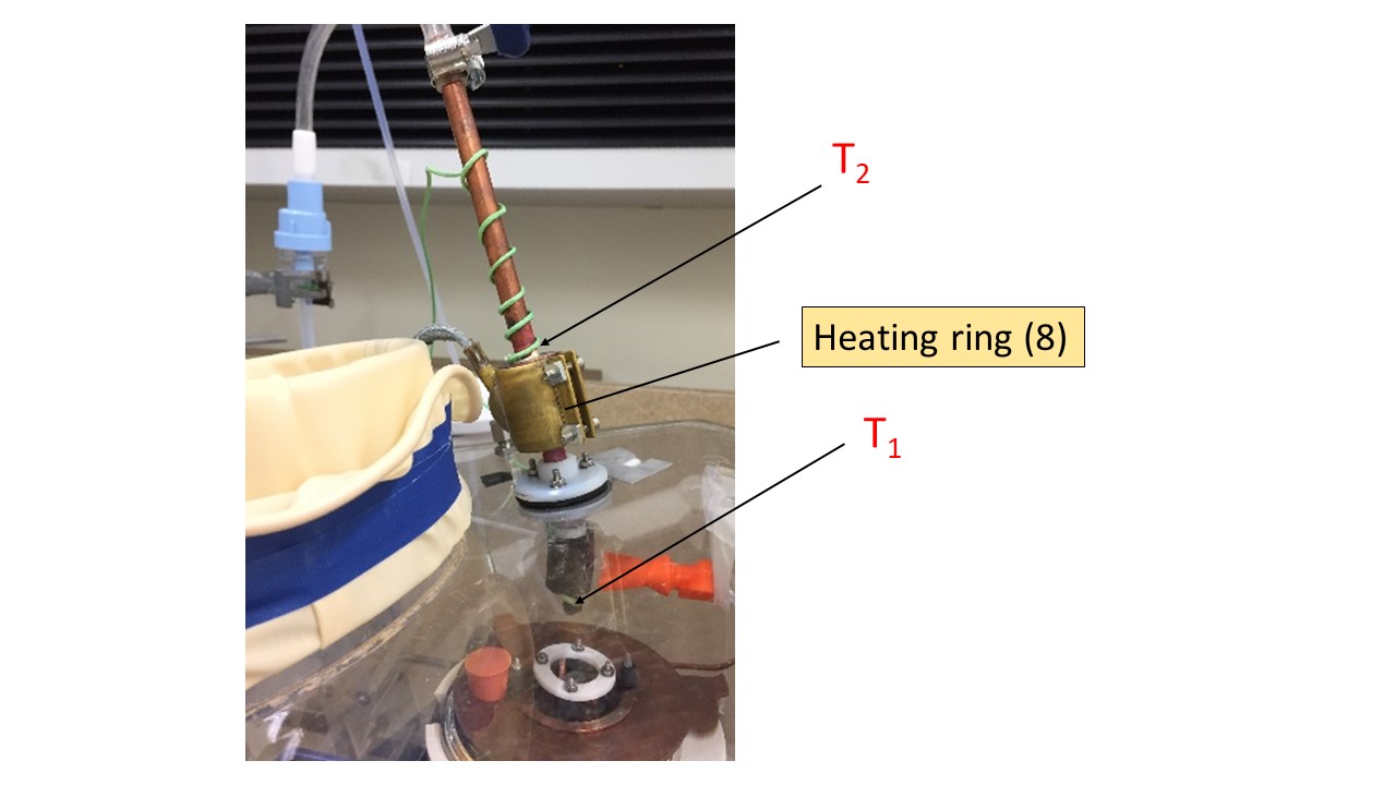
Fig. 4 Nozzle setup showing heating ring attached around a copper cylindrical block. T1 is K type thermocouple fixed at the bottom of nozzle. T2 is K type thermocouple attached on top of the copper block.#
Because the nozzle is close to the liquid ethane level, incoming water droplets may be subject to freezing before entering the cryogen. This poses a problem as crystallization is expected to happen under those conditions. Temperature at the bottom of the nozzle is monitored using a K type thermocouple (T1 in Figure 5) and I aim to maintain this temperature above 0 °C preventing water droplet from freezing. A heat ring (Voltage) (8 in figure 5) is attached around a 1 cm thick copper block soldered to the nozzle with the purpose to act as a heat sink, warming up the whole copper nozzle. A second K type thermocouple (T2 in Figure 3) is attached to the top of the copper block to monitor its temperature. Both are connected to a PID temperature controller (Red lion). A PID loop allow the voltage of the heat ring to be controlled and adjusted with respect to the inputted copper block temperature. Various experiments have shown that an input temperature of 40 °C for T2 allows the nozzle temperature (measured by T1) to stabilize around 20°C. An alarm has been created such as the temperature of the copper block can’t exceed 50 °C to avoid droplets evaporation. Even though T1 can be below 0°C during the water introduction, no frost is generally observed growing on the nozzle aperture.
Once the time of introduction is passed (20 min), the water reservoir is disconnected from the pipe connecting it to the nozzle. This pipe must then be plugged to avoid releasing ethane gas in the laboratory atmosphere. Reaction vessel height can be lowered down and put aside of the nozzle to avoid remaining condensed water droplets falling into the cryogen. All those steps must be done carefully to avoid big chunk of ice that grew on the heat shield (3 in Figure 1) to fall into the cryogen before the particles have been recovered.
Particle recovery#
Once the water droplets have been successfully introduced into the cryogen, the next stage in the process involves the recovery of the particles formed. A PTFE membrane (4 in Fig. 1) containing 1 μm sized pores screwed to the bottom of a basket made of copper which is used to fish out the particles from the ethane. They will then be dispersed from the basket into a Dewar (DR in figure 1) filled with liquid nitrogen where they will remain stable. Explain why stable in Ln2, and why use of membrane (difference with cryo-SEM). Fig. 5 resume all the experimental steps necessary to recover the particles. First, DR (recovery Dewar) must be filled with liquid nitrogen as previously described. The heat shield is slowly removed, making sure that no frost is scrapped from it during the lift-up by the top of the basket (holding piece). Secondly, the membrane must be lifted-up until it is above the level of the cryogen for the liquid ethane to be drained away from the basket and the ice particles (3) in Fig. 5). This step is critical because some time needs to be allowed for the liquid to be drained, but the temperature of the particles is also increasing with time. The warming curve of a 3 μl water droplet removed from liquid nitrogen at ambient temperature reached -100 ˚C after only 4 seconds [], and that is our time constraint to handle the particles out of the cryogen (either ethane or Nitrogen). I find that the particles obstruct the pores and the liquid ethane is not drained efficiently, also this parameter vary with different experiment. This make the step 4) hardly reproducible and usually resulting in either freezing ethane in liquid Nitrogen or having to wait for a long time for the cryogen to be drained (or evaporated) thus losing the amorphic structure of the particles.
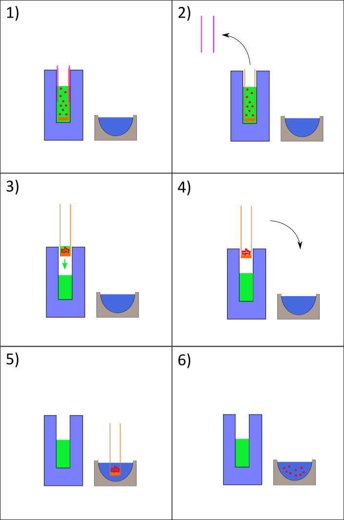
Fig. 5 Nozzle setup showing heating ring attached around a copper cylindrical block. T1 is K type thermocouple fixed at the bottom of nozzle. T2 is K type thermocouple attached on top of the copper block.#
However, after dispersion of the basket content within DR (5) in figure 6) we can visually observe that we obtain a milky mixture made of ice particles in liquid nitrogen.
:::{warning} Cleaning - Ethane is let evaporated while purge on – different pieces cleaned with ultrasonic bath :::
Testing and preliminary results#
2 different sets of experiments have been performed with complementary results. Neutron scattering allow for determination of bulk properties of ice and the surface structure of the particles. Optical microscopy allows for direct imaging, thus determining particles size and size distribution.